 Sondehunt
On 29.07.2019, on my way back from the Tomorrowland Festival in Belgium, I organized a trip to the KMI in Uccle to bring back my two Belgian ozone sondes and visit the institute and attend an ozone sonde launch.
The KMI has now had a continuous ozone measurement series of radiosonde ascents for almost exactly 50 years. Launches are always Mon, Wed and Fri at 11:30 UTC. ECC ozone sondes are used, since the middle of the 90s, before Brewer-Mast sondes were used.
In general a normal radiosonde, here a Vaisala RS41, is used for ozone sounding. The ozone measuring device is connected to this sonde, which consists of an electrochemical reaction cell, a sampling pump, a control board and the necessary batteries, and is connected in a polystyrene box. If you don’t already know it, take a look at the Vaisala Ozone Sounding Guide, which is very good and detailed.
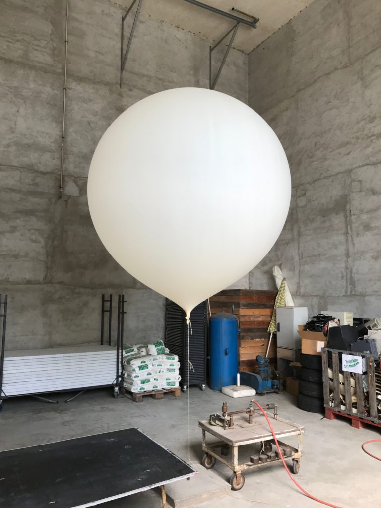
The preparations on the launch day start with the electrochemical testing of the cell starting at 7:30 UTC. We reached the institute at 9:00 UTC and were immediately taken into the balloon hangar to inflate the balloon. 1200 g balloons from Totex are used, which are filled with hydrogen to a counterweight of 2400 g. The hydrogen storage is located about 30 m away from the balloon hangar and is connected to it via underground piping. When the takeoff volume has been reached (the balloon is a considerable bit larger than a normal helium balloon from the automatic launch system despite the hydrogen filling), the balloon is tied up with cord and attached to the parachute. The balloon is removed from the filling device and attached to a weight, the cord between parachute and probe is measured and attached to the parachute.
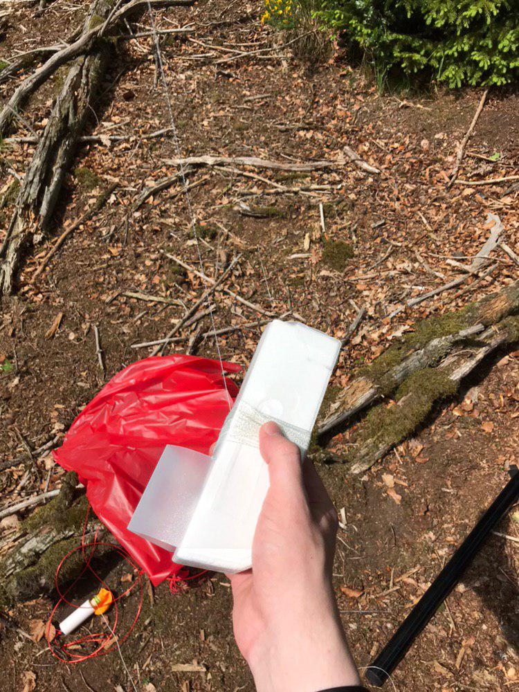
Then we went on to the laboratory where the electrochemical preparations take place and which is located in the basement of the institute. This is where the ozone sonde supplies and the test station are located. During the preliminary examination for the next but one ascent, my sondes were handed over. For the staff in Uccle, it is okay if the finder opens the sonde to reduce the packing volume and to remove the batteries. The air intake hose is also replaced each time the sonde is launched.
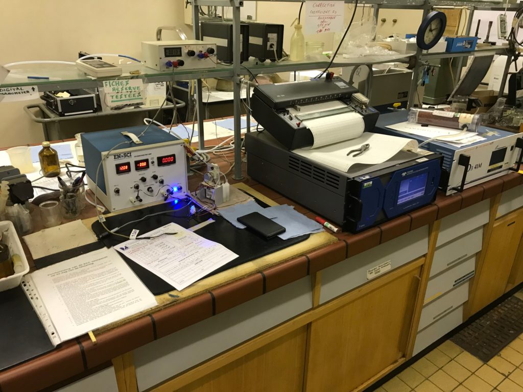
the electochemical teststation as described in Vaisalas manual 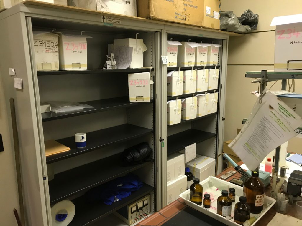
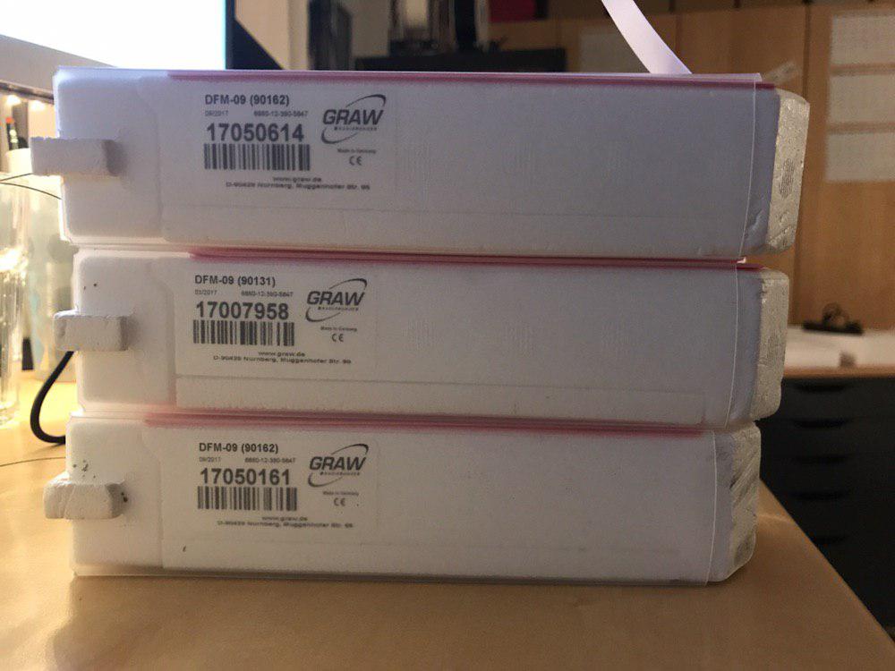
the supply of ozone sondes. On the day of my visit, a new sonde was used. The return quota is around 40%
The tour continued in the attic, where the receiving station and the ground check station are located. Here I got the opportunity to program the sondes I brought with me to a different frequency.
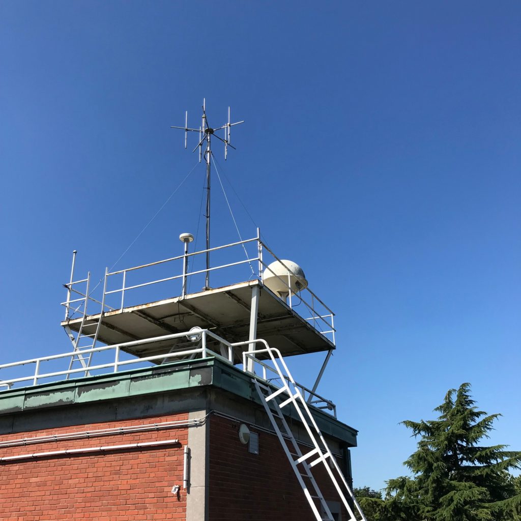
telemety and GPS antenna. Even the old radom from RS80/90 times is still on the roof 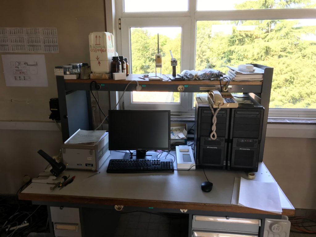
groudcheck and receive setup consisting of (older) SPS311, RI41 and MW41 software 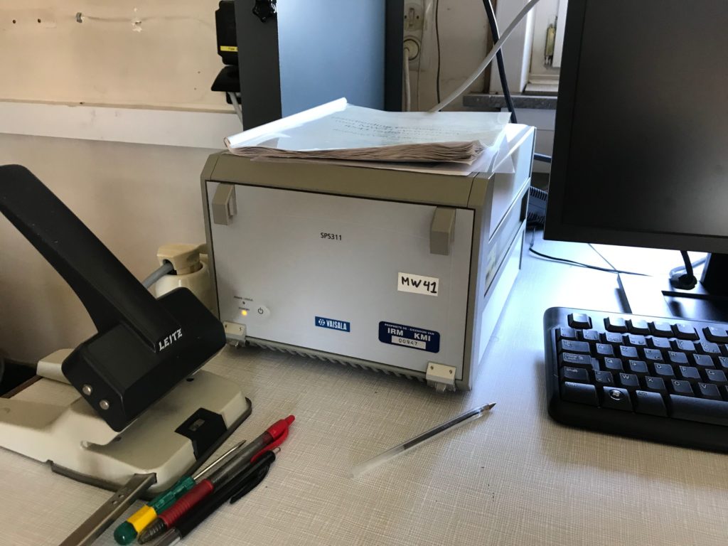
The older SPS311 were susceptible to the GPS rollover problem, Uccle could not perform any launches for two weeks 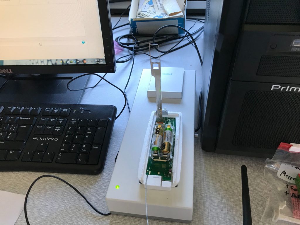
this is probably the first time for the RI41 seeing a “topless” RS41 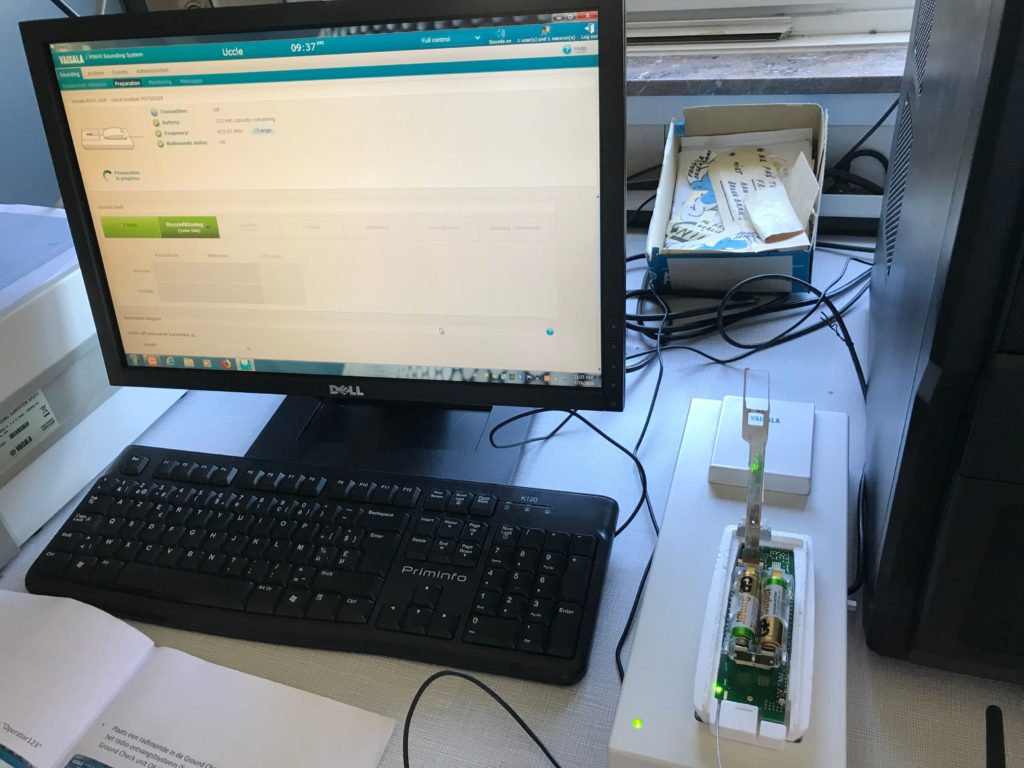
with 3 RS41 programed to german civil frequencies, nothing is to stop the first launches taking place in Gummersbach
About 1 hour before the launch the ozone sonde is brought up for the groundcheck. The heating battery is attached and the motor battery is fixed in the battery compartment. Since Vaisala no longer distributes water activated batteries, Uccle switched to lithium batteries in spring as one of the last stations in western europe. Vaisala now supplies 2 9V lithium batteries instead of the water activated battery, which are already connected in series, fitted with the correct plug and glued shut.
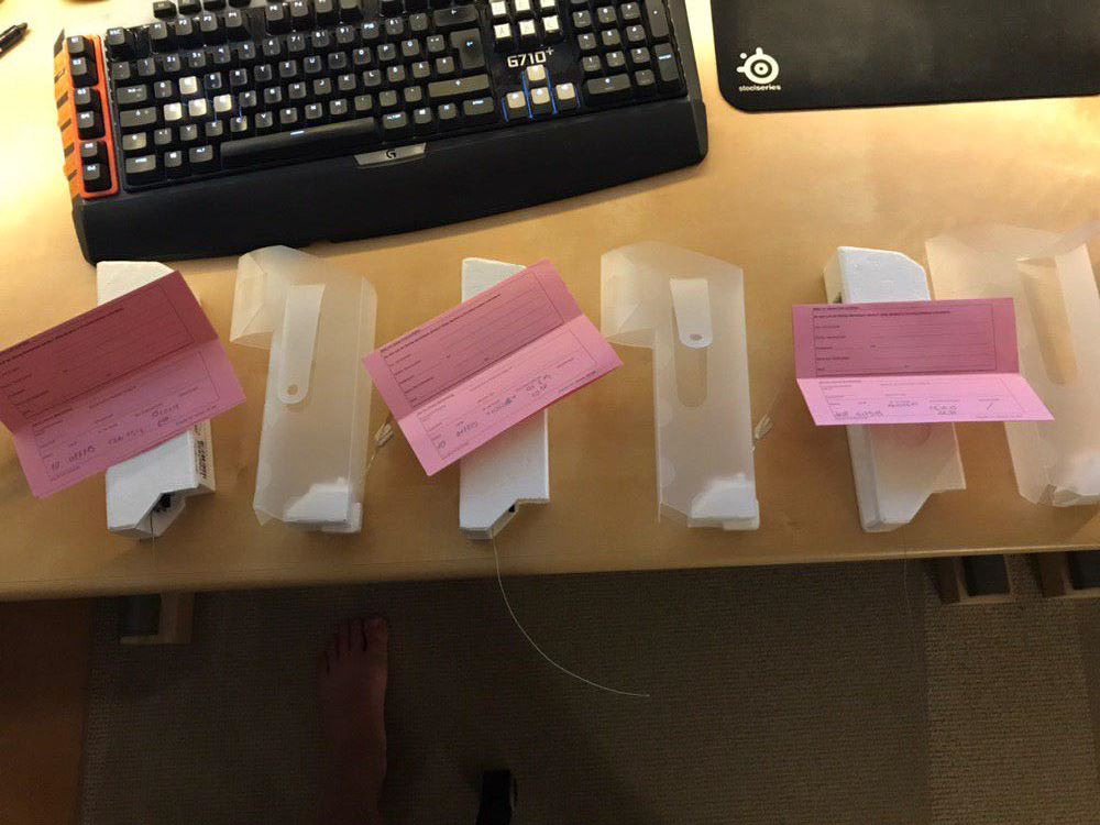
A radiosonde is unpacked and placed on the groundcheck device. After the ground check has been completed and the correction values for the ozone sonde have been entered in MW41, the radiosonde is attached to the ozone sonde. The motor is switched on and the motor current is controlled. Now ozone is flown into the sonde again and the measurement is checked before the motor is switched off again. The probe is then placed on the roof to obtain the GPS fix. The paper documentation of the sonde is entered into an online form and stapled together. The sonde is completely glued shut using tape.
the heating battery is attached and connected, as is the reaction cell 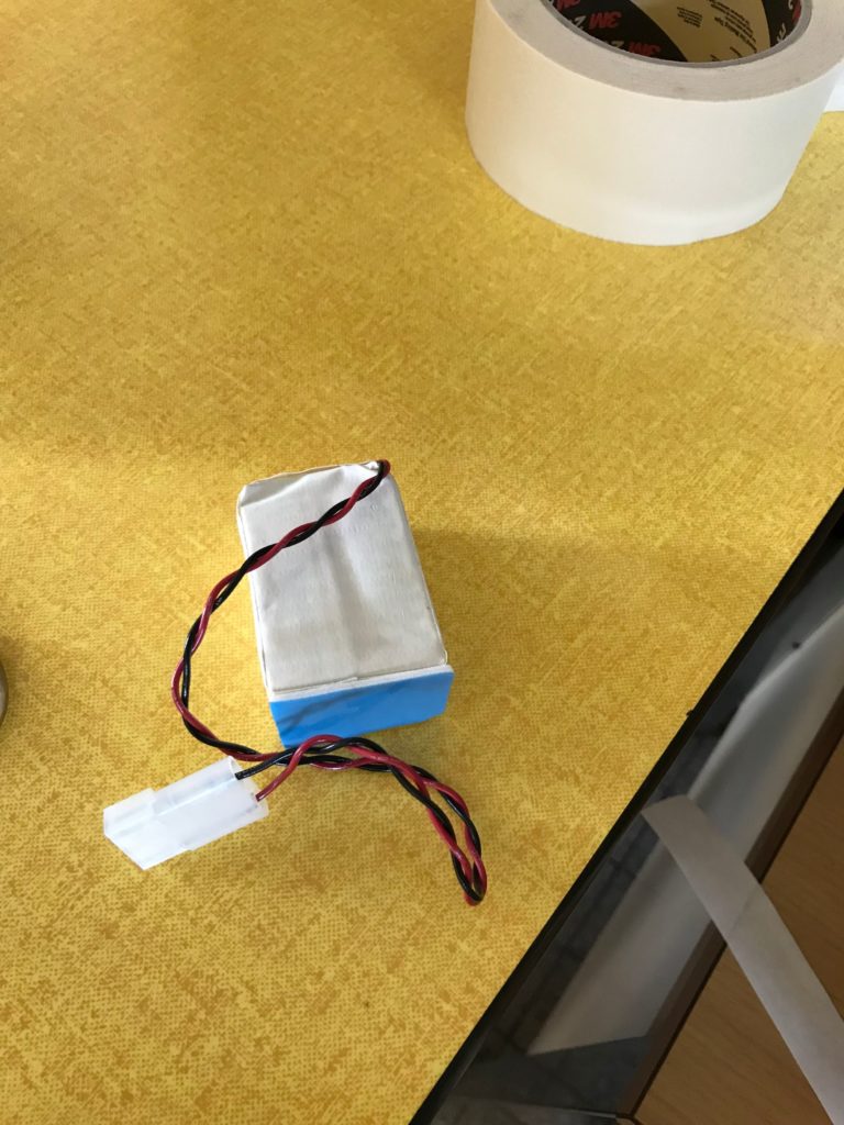
replacement for the water activated battery, as is supplied by Vaisala 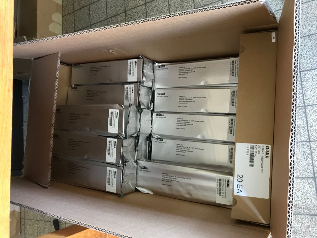
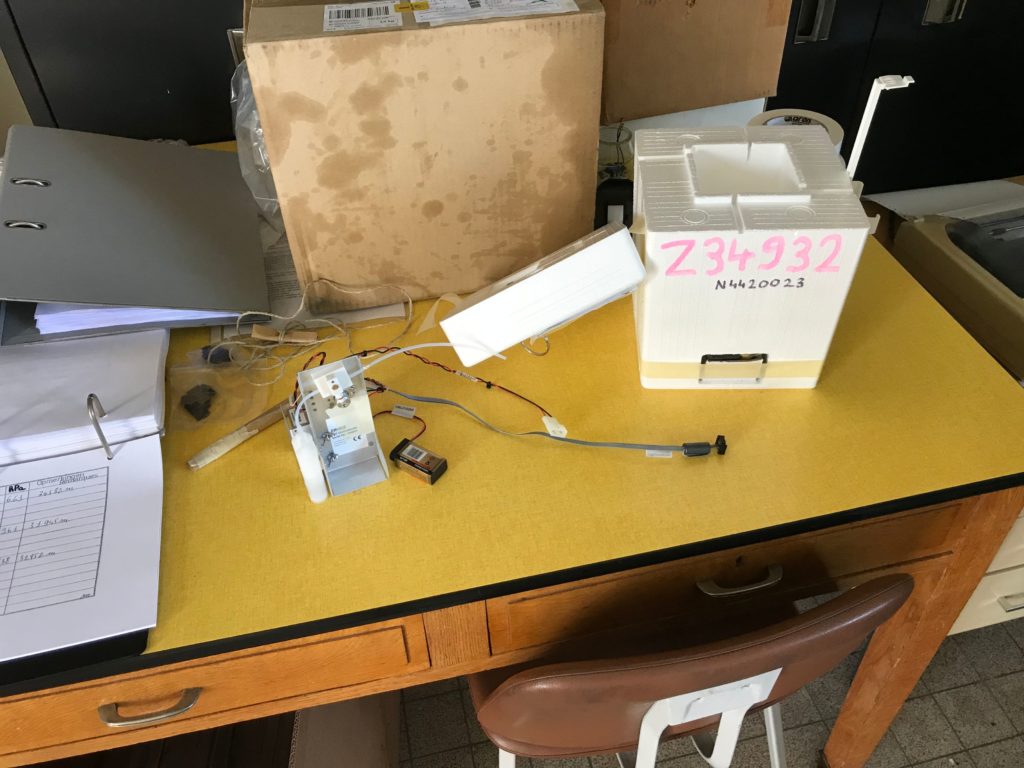
I would for sure love to have this box lying around 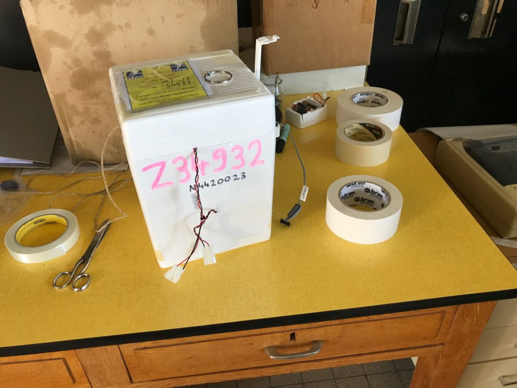
ozone sonde mostly finished 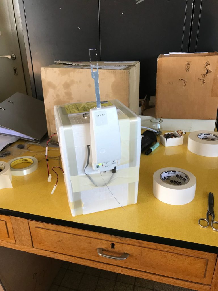
glued shut and after the groundcheck, 30 minutes till lauch 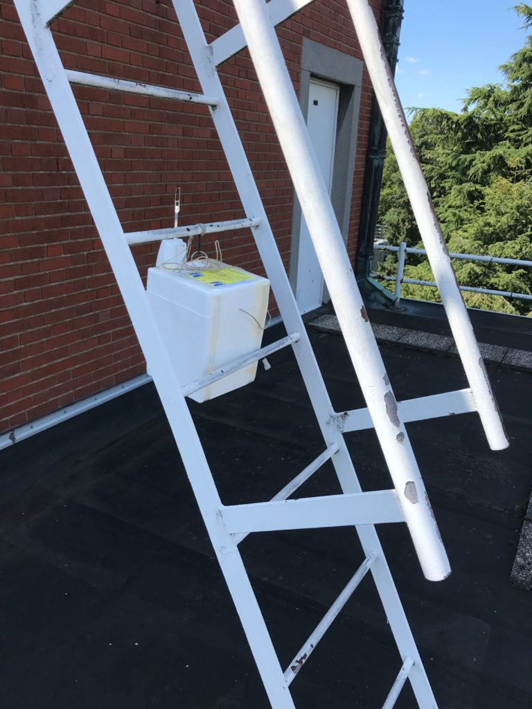
sonde ist getting it’s GPS fix
15 minutes prior to launch, the values of the ground-based weather station are entered in MW41 and supplemented in the documentation. The sonde is brought into the balloon hangar and fastened with both cords (one serves for the improvement of the flight stability) to the long cord leading to the parachute.
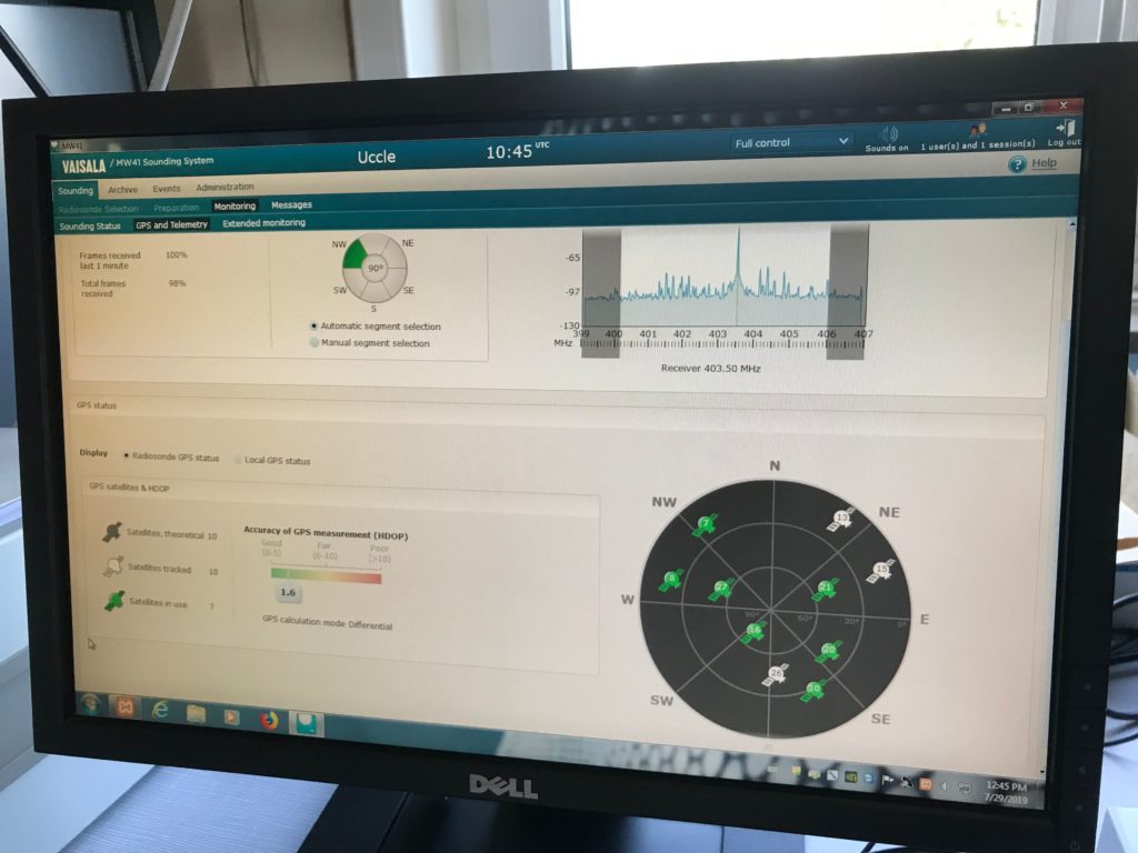
good GPS fix 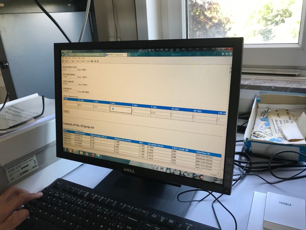
internal docomentation 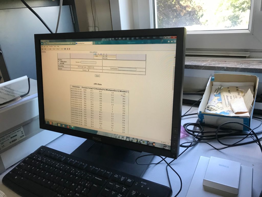
on various 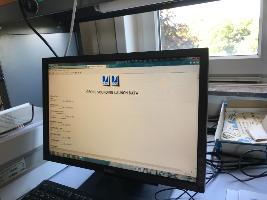
web UIs
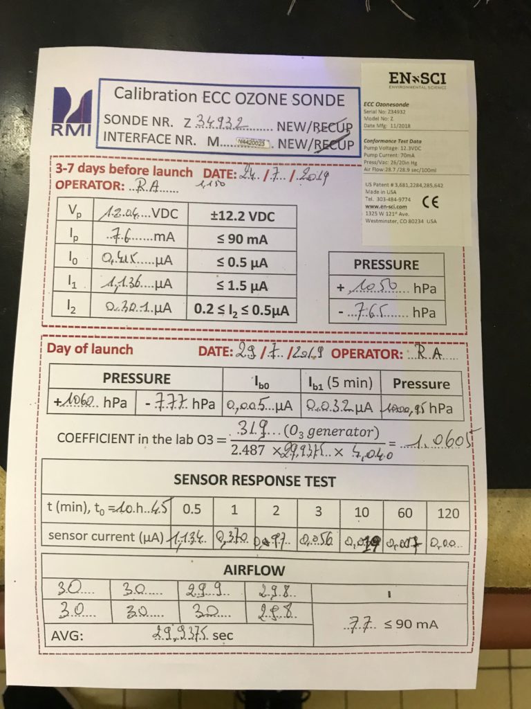
documentation of the ozone sonde calibration prior to launch 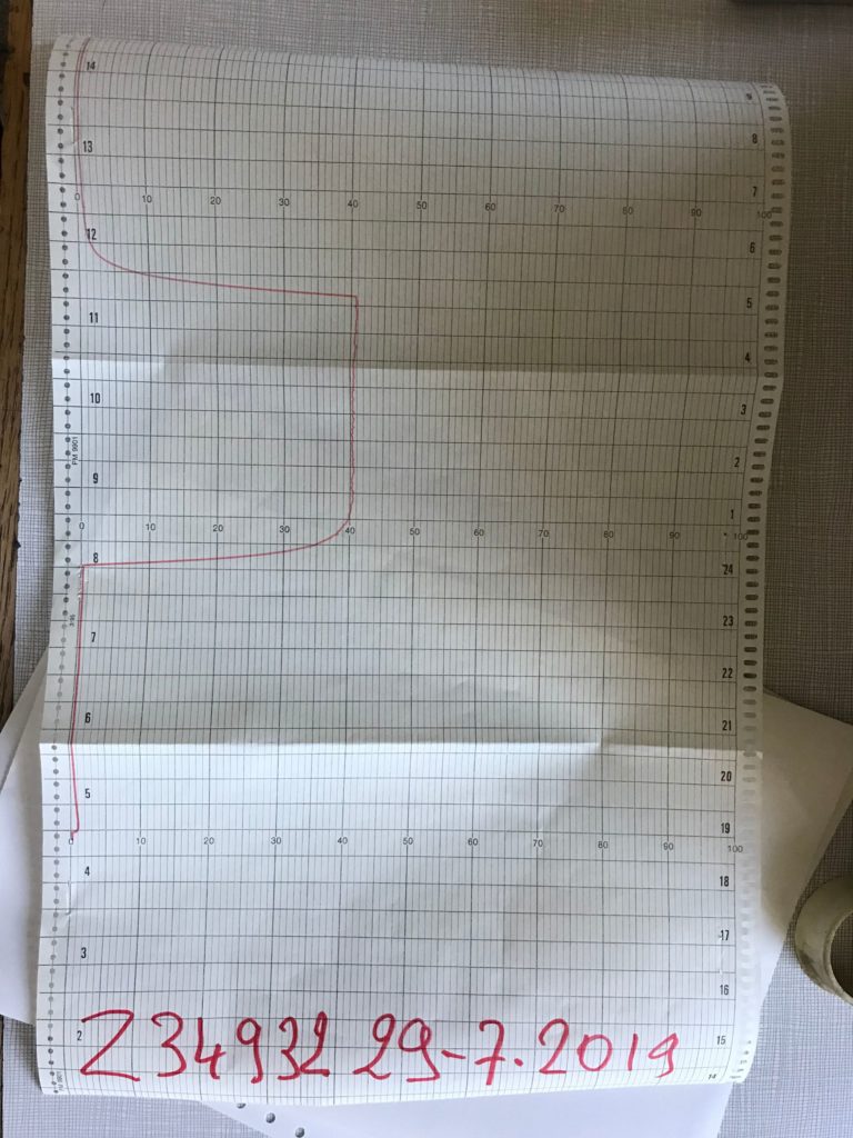
a real paper plot shows the response of the sonde when being exposed to ozone 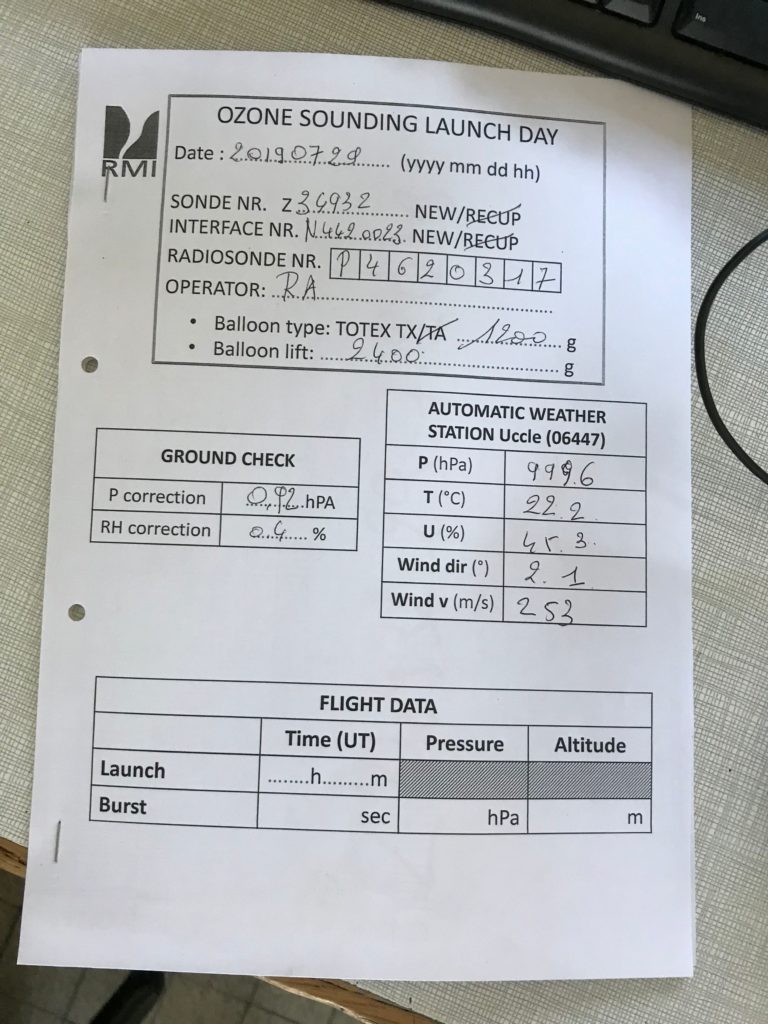
documentation on the lauch day
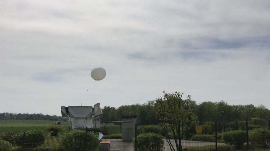
A second employee now exits the hangar with the sonde, and the assembly as a whole is brought to a nearby meadow. The balloon is risen gradually. Now was my moment: I was allowed to hold the sonde and wait until the time for the launch had come. Then I released the sonde on its journey, which took it west of Antwerp.
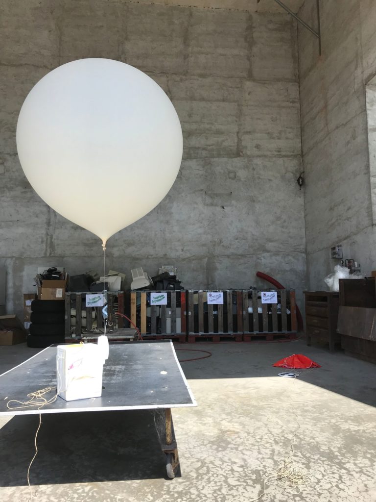
finished assembly for the ascent 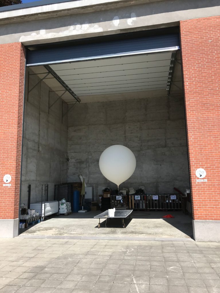
the ballon hangar has now been opened as well 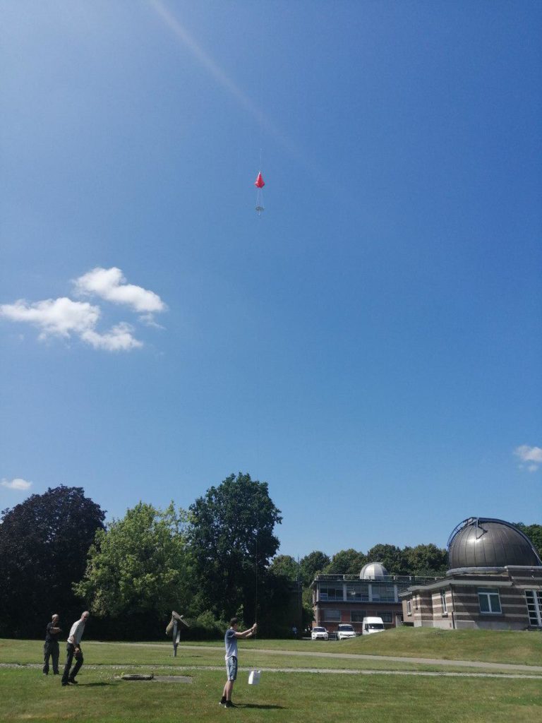
I am allowed to perform the launch! 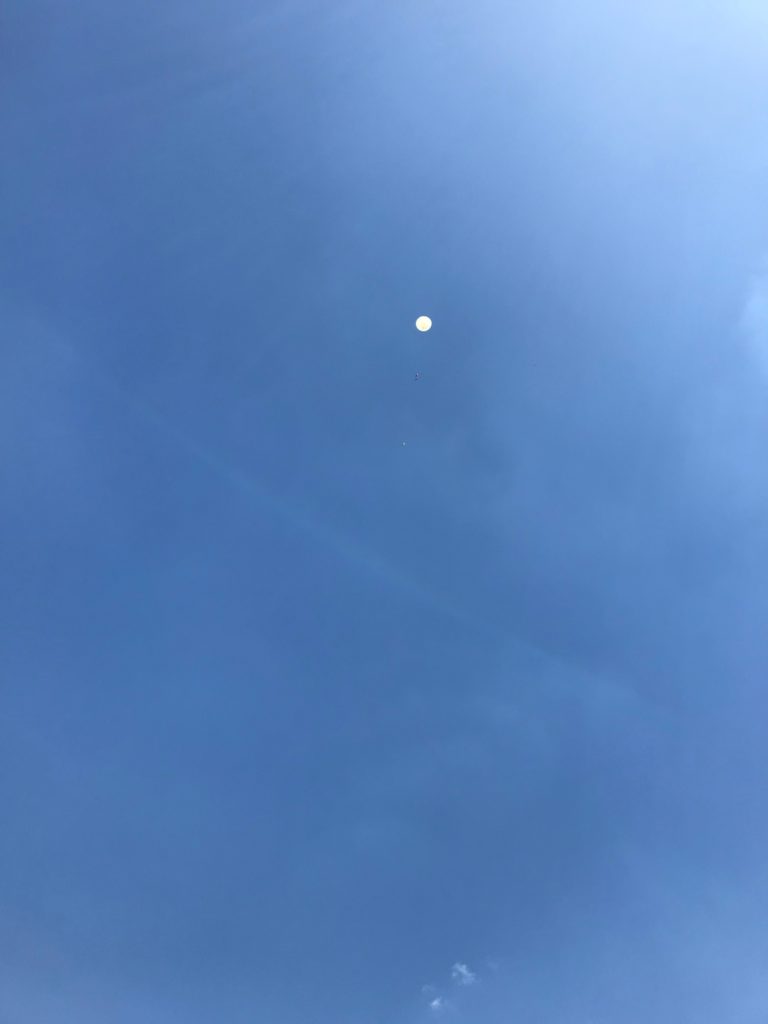
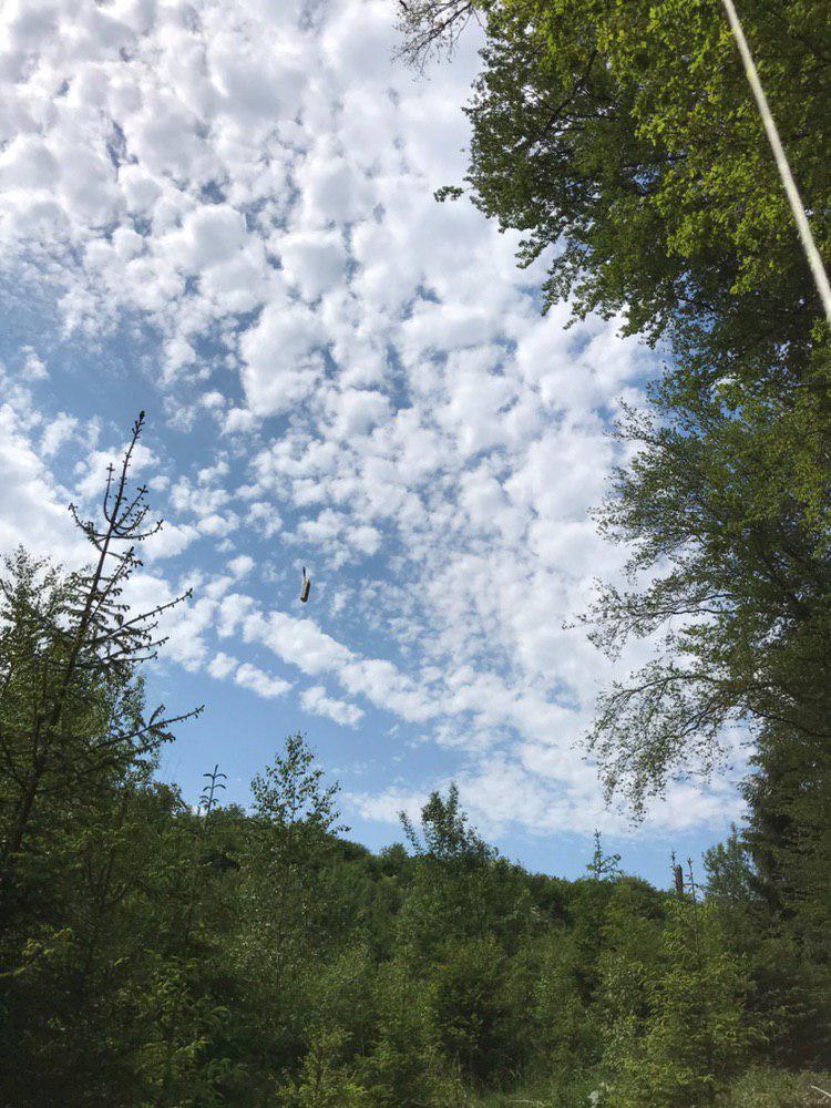
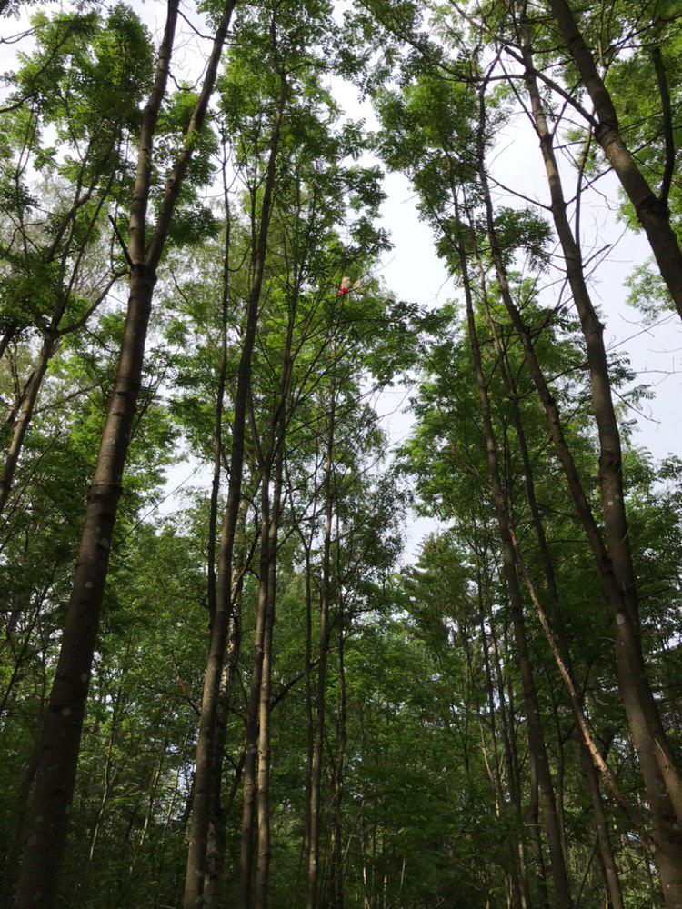
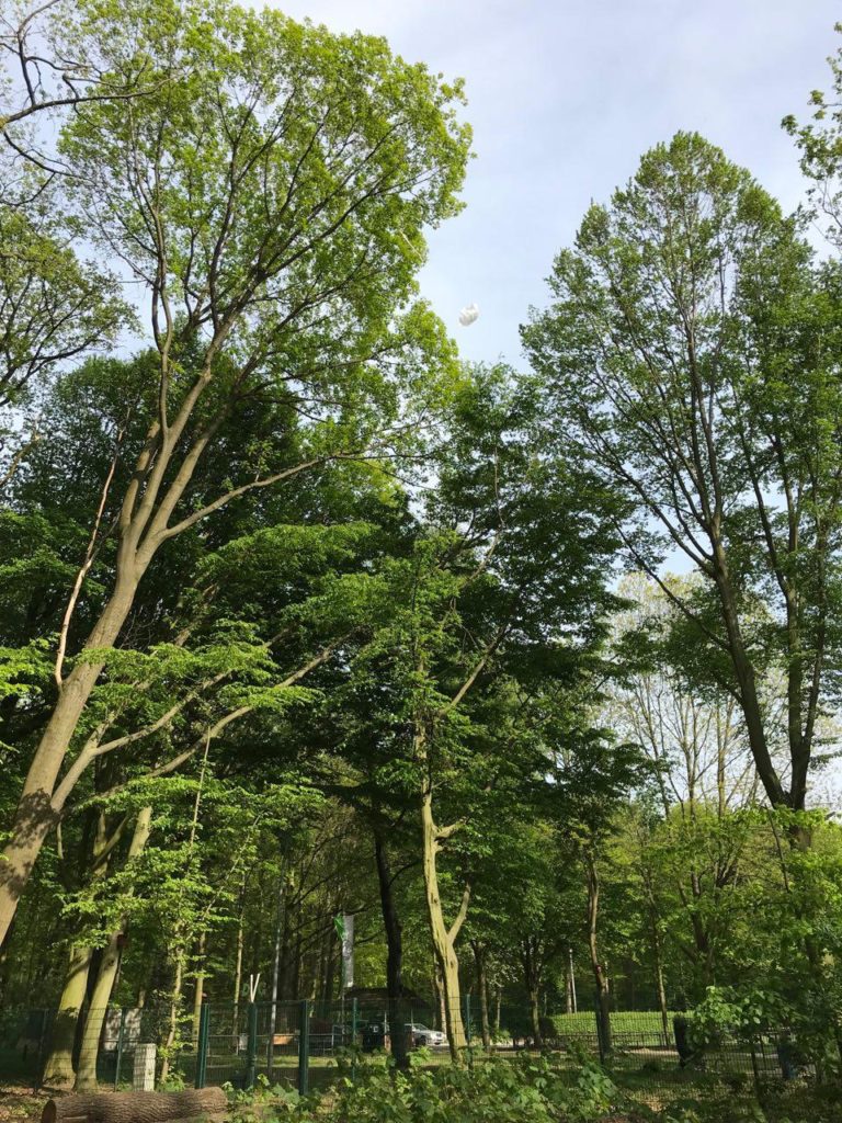
there she goes, still to be visible a few minutes later
I would like to thank Roger Ameloot, Roeland van Malderen and the whole KMI team for giving me this great insight into their work!